4 Wheeled Robot Design Basics and Challenges
Challenges in 4 Wheel Drive Robot Design
(Differential Steering)
Hi today we are going to discuss some of the basics of physical designing and selecting a chassis for a 4 wheel drive Robot for beginners. For this topic we are specifically going to see some of the design oriented challenges that come in the way of designing a 4 wheel robot that uses Differential Steering for taking turns (left and right) or to make a Complete 360 Degree in-place (pivot) rotation (zero-radius turning). Attention to some basic details can help a beginner to make an efficient robot without loss of much energy and torque.

There are many approaches that can be followed for steering a 4 wheel robot, such as the famous car-type steering (Ackerman steering), Cab-Drive Steering, Omni Directional wheels and the Differential Steering method, where the speed of the wheels are altered to change the direction or to take turns.
Ackerman and Cab-Drive steering requires complex design and additional drivers, servos and logic to control the robot, we will see these modes of steering in the later tutorials, For the beginners perspective it is good to start with the basic Differential Steering method, which for a simple model usually does not require any additional motors or mechanism.
Differential Steering is nothing but creating difference in the speed of the adjacent left or right wheels to take turns. For a complete 360 spin at its pivot position the two wheels on each adjacent side (left and right ) must rotate on opposite spin at same speed. This approach might appear easy, but it is not always efficient with all kinds of 4 wheel chassis.
Pivot Rotation of Robot
With enough torque, moving forward and backwards is not much of a big problem for a robot with 4 wheels, but the difficult part is to take an efficient complete 360 degree turn at its position. It not only looks cool but also has lot of advantages, such as ability to take turn in very less space.
If a Robot operating on principles of differential steering is performing poorly while taking turns even on a flat surface then there might be many reasons behind it. One of the most common mistakes that beginners do is with the selection of the chassis! By the time it comes into the consideration it is already too late to change the entire suspension.
Basic Designs
Given below are 3 most basic designs of chassis that are commonly available in stores or online for hobbyists. Which design would you think would perform best on a differential steering arrangement for an in-place 360 Degree turning?

Note: Essentially to carry on with this piece of article the reader is suggested to go through the basic definitions such as, Torque, wheel slip, Differential drive, and Traction. It is not necessary to have a thorough knowledge of the above mentioned topics, but just the basic knowledge is just fine.
As mentioned before, differential steering approach might appear easy to implement for beginners, for the robot to take complete turn at its position , because all you have to do is to make the wheels spin in opposite direction, but there are other factors that need to be taken into consideration or the robot might move perfectly in forward or backwards direction but when time comes to move left or right the robot might not even move from it position, and waste battery power and torque in an effort to take just a simple turn.
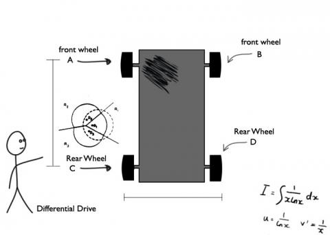
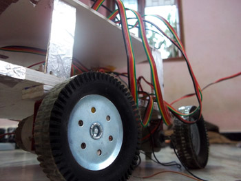
Let us consider the design one from the above three designs. Let us assume that pair of nice rubber wheels are installed on the design one. Also a pair of two DC motors with good amount of torque is installed on the rear wheels, which shall be responsible for the movement of the complete robot. Along with other equipment’s such as the power unit (batteries), the Circuit board with microcontrollers, sensors and other components, must add up some weight on the robot, resulting additional traction on the wheels.

Rubber wheels are installed to provide better traction and grip on the surface. No matter how powerful the motor might be, or no matter how much torque is applied (with additional gears), if the wheel slip occurs then it would result in loss of torque, hence for a better efficiency a good pairs of wheel are applied here. This arrangement is pretty much ok to drive this 4 wheel robot efficiently in a forward and backward direction, but what happens when this robot attempts to make 90 degree pivot turn?
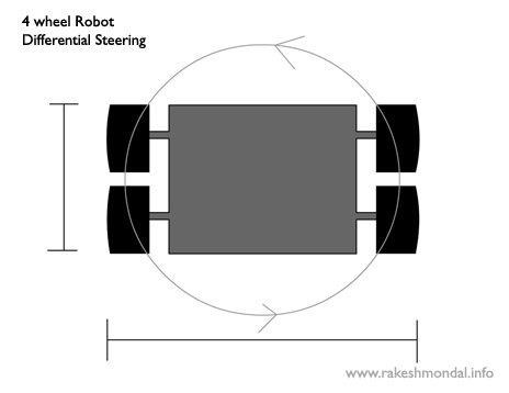
Notice that the distance between the Front pair of wheels (AC) and Rear wheels (BD), is too high as compared to the distance between the wheels on left pair (AB) and right pair (CD).
In an attempt to rotate left 90 degree, the rear wheels B and D spins in opposite direction which are connected to the Motor Drive, ( the wheel B rotates backwards and D forward) here by trying to make a left circular motion. But since the distance of the forward wheels A and C is too high from the rear B and D , hence it cuts out the circular pull generated by the back wheel which has a very less diameter (distance between B and D is the diameter).
Hence the front wheels A and C attempts to drag left. But high traction on front wheels (AC) exerts an opposing force making it more difficult for the robot to move left. Further if the torque generated by motors is not enough then the body would stay at rest making negligible turning. Adding more power would mean to add more batteries which would add up to the weight of the robot adding more traction on all the 4 wheels. (Traction on the wheel increases with weight).
This problem can be somewhat compensated by reducing the traction on the front wheels (using pair of sold plastic wheels instead of rubber wheels) which would allow the wheels to slip. But wheel slip might result in poor performance on rough terrain, hence not an efficient method to adopt.
This condition becomes worse when all the 4 wheels have individual motors for driving it, where the circular pull generated by both the front and rear wheels hampers each other rotation.
Hence these types of chassis are best to be used with Ackerman steering, or it would result in unnecessary loss of torque and battery power to take just a simple turn, moreover the turning itself would also not be efficient enough.
When it is not possible to change the chassis, Either omnidirectional wheels can be possible solution or a Tank like arrangement can be installed, but both would definitely add up to the cost of the robot more then what you have planned for.
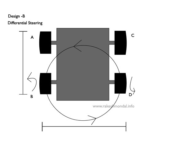
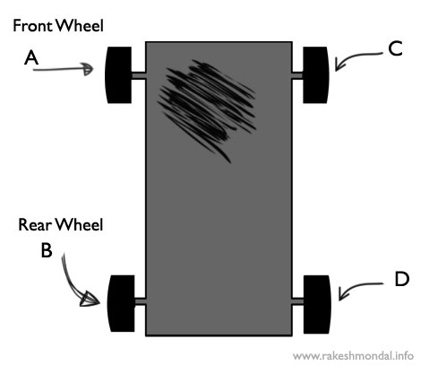
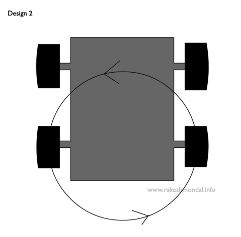
Let us consider this design two. Please note the distance of the front and rear wheels, and also the distance between the left and right wheels.
Let us assume that same set of motors and rubber wheels with good grip are installed on this design2 as it was installed on design 1. Please note that only difference here is that the distance between the set of front and rear wheels is almost the same as that of distance between the set of left and right pair. On performing the experiment with this chassis, would result little better performance than that of the design 1 because of the reduced distance, but still the front wheel should come in the way of the circular pull generated by the back wheels causing the front wheels to slip in circular motion.
I recently got a similar kind of chassis from a local shop for experiment, and results were better than that of the design 1.
But the opposing force was still acting on the front wheels but it was still allowing the front wheels to slip enough to make a turn, but it was very slow and clearly the torque from the motor (Engine) and battery power was getting unnecessarily wasted.
Merely the motion was totally dependent on the wheel slips occurring on the set of front wheels.
Here is the video of the chassis that I got from a local store.
Notice that robot is barely able to rotate at its position, that too because of the wheels slip occurring on the front wheels. If we are adding little more weight to this structure then traction on the front wheels must increase, which should make it more difficult to take turn.
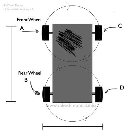
After experimenting with design 1 and 2, let us consider design three, here the distance between the front and rear wheels is reduced to the extent that it is way less than that of the distance between the left and right wheels.
Let us assume that design three is also installed with same set of motors applying same amount of torque, weight, traction on wheels etc. But here the distance of the front and rear wheels is far less as compared to previous two designs, plus the width of the robot chassis is increased.
In this design when the robot takes a zero-radius 360 degree turn (pivot turning), the front wheel gives almost negligible resistance to the overall circular motion generated by the rear wheels. Hence the torque applied by motors on each wheels gets properly harnessed, resulting in better performance without any drag or wheel slip while taking turn. Notice that turning of the body is not dependent on the wheel slips any more. Even if we add motors across all the 4 wheels, the result would be still better than other designs. Hence in this design you would not require omnidirectional wheels, or tank like wheels, a set of ordinary rubber wheels would do just fine (cost saving).
Some of the advantages that you get is out of this design are :- No loss of torque, fast turning, no wheel slips while turning, better traction on wheels, cost saving by use of regular wheels.
Conclusion
Decreasing the distance between the front and rear set of wheels, results in better zero-radius turning in any direction with 4 wheel drive robot. This is the reason why most of the successful robots posted across the web with 4 wheels which are efficient in rotating in pivot position (In-place) have very small distance in-between the rear and front wheels.
For example : https://youtu.be/sGGrLQy3cIA?t=2m19s
So we will keep these points in mind to make our robot as inexpensive as possible for beginners.
Related Topics
PIC18F4550 USB Interface Board
USB DC MOTOR Controller
L293D Motor Driver
PIC18F4550 Microcontroller