How and Why to use a Buck Switching Regulator

Switching regulator is complex to make (DIY) , and Linear regulator does its job at its best when you don’t have to worry about the input voltage and battery life, they are easy to setup, small and inexpensive - when you are working on your breadboard with unlimited source of power supply.
I have been quiet a fan of IC 7805 and mcp1702 due to their advantages, but it is not well suited when it comes to an arrangement where battery life and power consumption comes into serious consideration. While experimenting with some basic robots with linear regulator I have always faced challenges with the overall performance due to effect on the battery life, which ultimately converts to the number of hour or minutes you bot is going to work.
Switching regulators on the other hand are complicated to make one for your own but there are cost effective and small models available in the market which does the job decently.
Problem with Linear Regulator
Linear regulators are small and easy to install and use in any circuitry for the need of regulating the voltage but the result is loss of power and valuable battery power, in some cases even if there is no load across the circuit. It is estimated to a maximum of approx. 40% efficiency.
The change between the I/P and OP volts is liberated as heat, that is why IC 7505 gets heated up if the input voltage is somewhere like 20 volts. Either way, due to its small size and other factors, it has a solid reputation. However linear regulator costs battery life, especially if you are making a bot. hence the answer is Switching Step down Voltage regulator.
Alternative to Linear regulator (IC 7805)
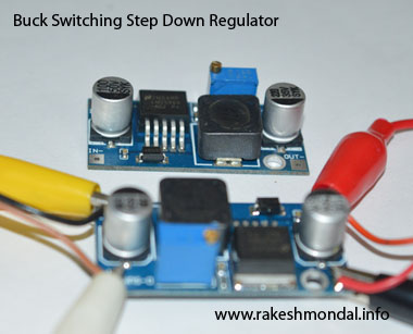
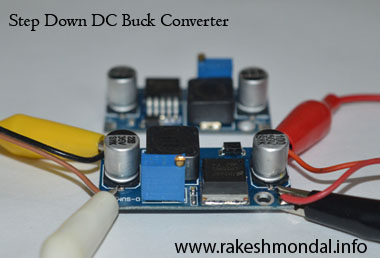
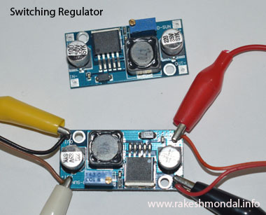
Buck switching regulator is one of the best alternative to Linear Voltage regulator. A Buck DC-DC Switching step down regulator is highly efficient and is an excellent alternative to various needs such as, regulating the voltage and also saving the battery life without much loss of power. This made it ideal for me to use them in my robots. There are many DC to DC step down switching regulators variable in the market at a very low cost. The efficiency according to data sheet rages from anything to 95%.
One of my favorite switching regulator model is DSWY2596 which used LM2596 IC. It is quiet inexpensive (50 to 60 Rupees, Indian Currency), I am not sure about the cost of this module in other countries but in India its equivalent is close to a dollar for a basic model. There are many versions of it, and some even comes with an LED and 7 segment display to get the voltage readings. One the most important feature of these Step down regulator is the ability to adjust and tune the output voltage with a potentiometer without additional hardware, so it makes it very easy to a project to adapt to the need of voltage levels.
Voltage Specifications
The input voltage can range from 4 V to 35 Volts. Make sure not to exceed 35 volts input to avoid damage (have seen capacitors explode). Output voltage can be tuned to 30volts output Max; for 5 Volts regulation the input voltage must be at least 7 Volts. Max input current is 3 Amps.
How to use a Buck Switching Regulator
It is very easy to use a buck switching regulator, but few things needs to be kept in mind before using it. Step down switching regulator comes with a potentiometer to tune or adjust the output voltage to the desired level.


First hookup a multi meter across the output pins without any load to the Regulator circuit, feed the circuit input pins with input voltage and then start tune the potentiometer in the regulator till the voltage readings on the output pins comes to desired voltage (example 5V). If you are experimenting with microcontroller or development boards then make sure not to connect the Buck step down regulator first to the microcontroller or any circuit before adjusting the voltage, or there is a danger of damaging the development board if the adjustment is incorrect.
Every time before you connect the buck switching regulator to your circuit, make sure to check the output voltage, this is because of the possibility of accidental tuning of regulator when not used for a long time, which can result in damage to the circuit.
Voltage drop happens across the output pins when the any load such as microcontroller is used. While in active state (with load), try not to throttle up the voltage output with potentiometer, or it will lead to damage. For example, say you are driving a led array or a stepper Motor with a microcontroller, and before connecting the output pins of the buck step down switching regulator to the microcontroller you have already tuned the voltage to 5Volts output, But after when the microcontroller starts its operations the voltage drops across the output pins of the regulator and you try to match it up to 5Volts again, this would lead to damage because the potentiometer on the switching regulator is quiet responsive and also when the load settles the voltage might be too much the microcontroller to endure leading to damage. So never try to tune the voltage while it’s in active operation unless you are 100% sure.
Thanks for Reading
Ron

